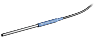
No longer available — please consider the F71 as an alternative.
Measurement Features
The Model 455 offers a variety of features to enhance the usability and convenience of the gaussmeter.
Autorange: In addition to manual range selection, the instrument automatically chooses an appropriate range for the measured field. Auto range works in DC and AC measurement modes.
Auto probe zero: Allows the user to zero all ranges for the selected measurement mode with the push of a key.
Display units: Field magnitude can be displayed in units of G, T, Oe, and A/m.
Max/Min Hold: The instrument stores the fully processed maximum and minimum DC or RMS field value. This differs from the faster peak capture feature that operates on broadband, unprocessed field reading information.
Relative reading: Relative feature calculates the difference between a live reading and the relative setpoint to highlight deviation from a known field point. This feature can be used in DC, RMS, or Peak measurement mode.
Instrument calibration: Lake Shore recommends an annual recalibration schedule for all precision gaussmeters. Recalibrations are always available from the factory, but the Model 455 allows users to field calibrate the instrument if necessary. Recalibration requires a computer interface and precision low resistance standards of known value.
Instrument Probe Features
The Model 455 has the best measurement performance when used with Lake Shore Hall probes. Firmware-based features work in tandem with the probe's calibration and programming to ensure accurate, repeatable measurements and ease of setup. Many of the features require probe characteristics that are stored in the probe connector's non-volatile memory.
Probe field compensation: The Hall effect devices used in gaussmeter probes produce a near linear response in the presence of magnetic field. The small nonlinearities present in each individual device can be measured and subtracted from the field reading. Model 455 probes are calibrated in this way to provide the most accurate DC readings.
Probe temperature compensation: Hall effect devices show a slight change in sensitivity and offset with tempera-ture. Probe temperature effects can be measured and subtracted out of field readings. A temperature sensor in the probe tip relays real time temperature to the gaussmeter, enabling compen-sation. Although temperature effects contribute only a small fraction of the overall probe measurement accuracy, temperature compensation will often improve measurement and control stability.
Probe temperature display: The gaussmeter can display the probe's temperature in °C along with a field reading when using a probe that includes a temperature sensor.
Frequency display: When operating in RMS mode, the gaussmeter can display the frequency of the measured AC field along with a field reading.
Probe information: The gaussmeter reads the probe information on power up or any time the probe is changed to allow hot swapping of probes. Critical probe information can be viewed on the front panel and read over the computer interface to ensure proper system configuration.
Extension cables: The complex nature of Hall effect measurements make it necessary to match extension cables to the probe when longer cables are needed. Keeping probes and their extensions from getting mixed up can become a problem when more than one probe is in use. The Model 455 alleviates most of the hassle by allowing users to match probes to extensions in the field. Stored information can be viewed on the front panel and read over the computer interface to ensure proper mating.
Hall effect generators (magnetic field sensors): The Model 455 will operate with a discrete Hall effect generator when a suitable probe is not available. Users can program nominal sensitivity and serial number into an optional MCBL-6 blank connector to provide all gaussmeter functions except field and temperature compensation. If no sensitivity information is available, the Model 455 reverts to resistance measurement.

Display and Interface Features
Display
The Model 455 has a two line by 20 character vacuum fluorescent display. During normal operation, the display is used to report field readings and give results of other features such as max/min or relative. The display can also be configured to show probe temperature or frequency. When setting instrument parameters, the display gives the operator meaningful prompts and feedback to simplify operation. The operator can also control display brightness.
Following are three examples of the various display configurations:

The display configured to show the RMS field value and frequency, and the probe temperature

The display configured to show both the Maximum and Minimum DC field values

The display configured to both show the positive and negative Peak readings
Alarm and Relay
High and low alarms are included in the instrument. Alarm actuators include display annunciator, audible beeper, and two relays. The relays can also be controlled manually for other system needs.
Voltage Output 1
The first voltage output gives access to amplified voltage signal directly from the probe. This voltage is corrected for the nominal sensitivity of the probe and provides the widest bandwidth of the three voltage outputs. In wideband AC mode, the signal can be viewed on an oscilloscope to observe the shape of AC fields. In peak mode, the output can be used to view a pulse shape or other characteristic of a momentary signal. Output 1 serves only as a diagnostic tool in DC and narrow band AC modes because modulation of the probe signal prevents a clear view of the field response.
Voltage Output 2
The second voltage output provides a voltage proportional to measured field with the benefits of some signal processing. The output is produced by the DSP through a fast D/A converter.
The output signal is updated at 40 kHz, giving good response for low to mid frequency fields. Signal quality degrades at high frequency because of the sampling rate. This voltage can be corrected for probe offset and for the nominal sensitivity of the probe.
Voltage Output 3
The third voltage output provides a voltage proportional to measured field with the most signal processing of the three outputs. All probe compensation available to the display readings, including temperature compensation, can be performed on this output. The output is produced by the micro-processor through a high-resolution, 16-bit, D/A converter updated at 30 readings per second.
Computer Interface
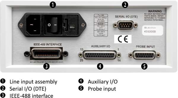
Two computer interfaces are included with the Model 455: serial (RS-232C) and parallel (IEEE-488). Both allow setup of all instrument parameters and read-back of measured values. The reading rate over the interface is nominally 30 readings per second but ranges from 10 to 100 readings per second are available. LabVIEW™ drivers are provided to instrument users—consult Lake Shore for availability.
Keypad
The instrument has a 22-position keypad with individual keys assigned to frequently used features. Menus are reserved for less frequently used setup operations. The keypad can be locked out to prevent unintended changes of instrument setup.

Stock probes
The most commonly ordered probes for this gaussmeter. Other Hall probes are available. Or visit the Hall probe selection guide.


